

Electric
steering gear system of ship
Electric tele-motor
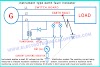
When bridge wheel is turned, it moves rheostat B and disturbing current flows to rotate the control motor. This is the same as we change the speed of our fan. Rheostat A will hunt back unless the balance is restored which will stop the control motor. This same we do an experiment of electric current by using a rheostat. Control motor drives a screw shaft via a flexible coupling in the control box and the screw block moves through the floating lever and causes movement to actuating rod and displaces the pumps on stroke. This rod moves side by side and that what defines the movement of the rudder. If the event of tele-motor failure occurs, steering gear can be controlled nearby by turning off control motor power and engaging with screw-shaft bevel gear with hand-wheel gear.Ward Leonard speed control steering gear system
Steering gear functioning which depends on the Ward-Leonard principle comprises electric control, electric power unit, and
electrical transmission work. The arrangement consists of a continuously running
motor-generator set which has a straight coupled exciter to provide the field
current of the generator. The main motor which drives the rudder has no input
and thus is motionless.

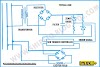
When the wheel on the bridge is turned and moves from one side to another side, and the rheostat contact moved, the control system is disturbed and a voltage occurs in the exciter field, the exciter, and the generator field. The generator produces power which turns the rudder motor and hence the rudder. As the rudder moves, it returns the rudder rheostat contact to the same position as the bridge rheostat, bringing the system into balance and stopping all current flow.
An electro-hydraulic steering gear system
Two types of hydraulically powered transmission units or steering gear are in common use, namely:a) Ram type.
b) Rotary vane type.
Depending upon torque needs, two variations are possible the two-ram and the four-ram. The rams acting in hydraulic cylinders operate the tiller by means of a swivel crosshead carried in a fork of the rams. A variable delivery pump which is mounted on each cylinder and the slipper ring is related by rods to the have power over the spindle of the tele-motor receiver.
Ram type steering gear
The changeable delivery pump is piped to each cylinder to enable suction or discharge from either. The whole hydraulic fluid is controlled by these motors. A replenishing tank is mounted close by and arranged with non-return suction valves which without human intervention provide make-up fluid to the pumps. A bypass valve is coupled with spring-loaded shock a valve that opens in the event of a very heavy sea forcing the rudder over. This maintains the position of the ship and load on the rudder. In moving over, the pump is actuated and the steering gear will return the rudder to its original position once the heavy sea has passed.Four Ram type steering gear
A spring-loaded relief linkage on the tiller will avoid damage to the managing gear during a shock movement. During the usual operation, one pump will be running and others will work as stand by units. But if a faster response is required, for instance in confined waters, both pumps may be in use. The pumps will be in the no-delivery state so that until a rudder progress is required by a signal from the bridge tele-motor transmitter. The tele-motor receiver cylinder will then move this will result in a movement of the floating lever which will move the floating ring or slipper pad of the pump, causing a pumping action. The fluid will be drawn from one cylinder and pumped to the other, thus turning the tiller and the rudder.The basic principles of operation of two-ram and four ram gear are similar except that the pump will draw from two diagonally opposite cylinders and discharge to the other two. Two discharge valves are present on one side while two-valve of the inlet are opposite sides. The four-ram arrangement provides greater torque and the elasticity of different arrangements in the event of component failure.
Either the pump can be used with all cylinders or with either the two-port (left-hand side) or two starboard (Right-hand side) cylinders. Various valves must be opened or closed to provide these arrangements. The use of a direct valve block incorporating rudder shock relief valves, pump isolating valves, ram isolating and bypass valves offer greater flexibility with four-ram steering gear. In normal operation, one pump can operate all cylinders. In an emergency situation, the defective cylinders could be isolated and the operation of steering gear resumed.
Rapson slide arrangement
The crosshead arrangement on the four-ram type steering gear incorporates the 'Rapson Slide'. This provides a mechanical benefit which increases with the angle turned through. The crosshead arrangement may use either a forked tiller or around arm tiller. The round arm tiller has a center crosshead which is free to slide along the tiller. The straight-line movement of the rams is thus transformed into an angular tiller movement. In the forked tiller arrangement, the ram movement is transferred to the tiller through swivel blocks.Rotary vane type steering gear
This is equivalent to a two-ram gear, with torque capacities depending on size. An assembly of two rotary vane gears, one above the other, or with two independent hydraulic circuits with self-closing lock valves provide the security of four ram gear.As you can see the diagram, rotor C is fitted and keyed to a tapered rudder stock A and the stator B is protected to the ship's structure. Fixed vanes, secured equidistantly in the stator bore and rotating vanes secured equidistantly in the rotor, form two sets of pressure chambers in the annular space between the rotor and stator. They are interconnected by a manifold. Three fixed and three moving vans are normal and permit a total rudder angle of 70°, i.e. 35° in each direction. The fixed and rotating vanes may be of spheroid graphite cast iron. This is done because of the surface finish of cast iron. They are securely fixed to the cast steel rotor and stator by high tensile steel dowel pins and cap screws. Keys are also fitted along the length of the rotary vanes, for mechanical strength.
The vanes fixing is well thought-out to be of enough strength to make them suitable to act as rudder stops. Their strength is to be more than the other parts because of a lot of loads face by these parts. Steel sealing strips, backed by artificial rubber, are fitted in grooves along with the operational faces of the fixed and rotary vanes, thus ensuring high volumetric efficiency, of 96-98% even at the relief valve pressure of 100 bar or over. The anchor brackets are securely bolted to the ship. This clearance varies with each size of the rotary vane unit but is approximately 38 mm in total and it is necessary that the rudder carrier should be capable of restricting the vertical movements of the rudderstock. But if vertical motion is large then it can damage the arrangement of steering gear present.


1 Comments
I would like to thank you for the efforts you’ve put in writing this blog website. I really hope to check out the same high-grade blog post content from you in the future as well.
ReplyDeletePolyester Rope Suppliers
We love to hear your comments on this article, so that we may better serve you in the future.