


Insulated neutral system or isolated neutral system (INS)
Insulated system
An insulated system is the one that is totally electrically
insulated from earth (ship’s hull)
Reason for using an insulated system
The priority requirement on board ship is to maintain
continuity of the electrical supply to equipment in the event of a single earth
fault occurring. On an insulated system,
one earth fault does not interrupt the supply but raises a warning on the
earth's detection system. This allows
the operator to locate and clear the fault.
Advantages of insulated neutral system
Avoids the risk of loss of essential services like steering
gear
One earth fault doesn’t interrupt the supply but an earth
fault detection system will give warning
Earthed system
An earthed system has one pole or the neutral connected to
earth
On board ships, the main system is normally insulated for the bus
bar voltage of 440 V
When the voltage exceeds 1000 V, then the neutral of the
alternator has to be earthed.
Neutral earthing
As mentioned earlier, for the systems having more than 1000
V, the neutral will be earthed. To
protect the system against the high fault current, normally the neutral is
earthed either through a resistor or a transformer. In the case of an earth fault, it is
preferable that the fault current should not exceed the full load current of
the alternator.
What is Earth fault?
An earth fault is due to a break in the insulation, allowing
the conductor to touch the hull or an earthed metal enclosure.
What is an Open circuit fault?
An open circuit fault is due to a break in the conductor so
that the current cannot flow.
What is the Short circuit fault?
It is due to a double break in the insulation, allowing both
conductors to be connected so that very large current passes or short circuit
occurs. The fault current depends on the
overall impedance in the circuit at the time of the fault.
What are the Causes of short circuit?
A short circuit may occur because of the breakdown of
insulation due to overheating or ingress of moisture/water.
Terminal connections become loose due to vibration or any
other reasons, thereby two cables come into contact.
Cables exposed to fire, mechanical damage, cuts, etc. may
lead to short circuits.
Earthing of electrical equipment
In order to protect against the dangers of electric shock
and possible fire hazard, the metal enclosures, and other non-current-carrying
metal parts of the equipment must be earthed.
This enables the potential at the time of earth fault to become zero and
also provides the least resistance path for the current to flow to the
earth. (Ship’s hull).
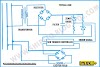
 |
| CORE BALANCE CURRENT TRANSFORMER |
Significance of earth faults
If an earth fault occurs (assuming an earthed system), it
would be equivalent to a short circuit fault via the ship’s hull. The resulting large current would immediately
blow the fuse and supply to the equipment is cut off. If this happens to essential equipment like Steering gear, then the ship will be having loss of control. The large current could also cause arcing
damage at the fault location.
What are the Causes of earth faults?
- Dampness
- Mechanical damage
- Contamination due to dirt
- Temperature rise
- Ageing
Prevention of earth faults
- Appropriate types of the enclosure should be used to prevent the ingress of moisture and dust
- Make sure protection against the mechanical damage
- Exact cable glands and seals are to be used on cable ends
- Insulation tests are to be performed on a regular basis
- Maintaining the equipment strictly as per PMS
Effect of a single earth fault
A single earth fault occurring in an insulated distribution
system, will not cause any protective gear to operate and the system will
continue to function normally. The single earth fault does not provide a
complete circuit so no earth fault current will exist.
Effect of two earth faults
If an earth fault occurs at B on another line, the two earth
faults would be equivalent to a short circuit via ship’s hull and cause
protective gears to operate
An insulated system is, therefore, more effective than an
earthed distribution the system, because the insulated system requires two earth
faults on two different lines to cause the tripping of the equipment.
Earth fault indicators
Regulations require that earth fault indicators are fitted
to the MSB to indicate the presence of an earth fault on each isolated section
of a distribution system. Earth fault
indicators can be a set of lamps or an ohm meter calibrated in k Ω to show the
system insulation resistance value to earth.
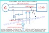
Earth fault indicator using lamps

If the system is healthy (no earth faults) then the lamps
will glow with equal brilliance. If an
earth fault occurs on one line, the lamp connected in that line is dim or
extinguished and the other lamps glow brighter.
The disadvantage of this system is that it is not very
sensitive to indicate the presence of high resistance/impedance faults.
Earth fault indicator using ohm meter
This system can incorporate a switch which will give off an
alarm when the insulation resistance falls to the set value. A small DC voltage is injected into the
distribution system. Resulting current
indicates the insulation resistance. The
maximum earth fault monitoring current is 250 μ A.
An alternative arrangement for k Ω meter
Common locations of
earth faults in the ship
- Lamp fittings on the open deck.
- In the laundry, washing machines drenched with water
- In the galley, the ovens, hot plates, etc.
- Dripping of water over electrical machinery.
- Condensed moisture in the motor terminal box.
- Overheated motors leading to the melting of varnish on the windings.
- Dirty electrical apparatus with surface tracking (leakage current)
- Terminal lock nuts becoming loose due to vibration etc., leading to cable touching the body.
- Due to aging, the insulation may crack due to brittleness, leading to possible earth faults.
Treatment of earth faults
- Earth faults should be eliminated when located.
- Damaged conductor insulation has to be repaired or renewed.
- Dampness or moisture has to be removed by gentle and gradual heating using lamps.
- Machinery should be kept clean of dirt and dust.
An insulation meter with 3 modes
- Monitoring
- Fault finding.
- Test.
What is the difference between monitoring and fault finding?
Application of three modes of an insulation meter:
Monitoring: to check the healthiness of the insulation of
motors, Cables, etc. by measuring the IR values.
Fault Finding: insulation meter/megger can also be used to check the continuity of cables, motor windings, etc. To find the O/C fault.
Test: to check the insulation meter is ok or not. Is there 1000V or 500V is available or not. Sometime battery/cell may be discharged of digital Meter.
What is a Neutral Earthing Resistor (NER)?

The neutral earthing resistors are commonly used to handling
the fault currents. NER is also called Neutral Grounding Resistors. NER is used
in the AC distribution system to limit the transient overvoltages that flow
through the neutral point of the alternator to a safe level during a fault condition.
Generally, NER is connected between the neutral of the generator and the ground. NERs limit the fault currents to a value that keeps away from damage to
equipment, so far permit the adequate flow of fault current to activate protection
devices.
NERs must withstand a huge amount of energy for the duration
of the fault condition as per IEEE32 standards. Therefore the selection of an
NER is highly important to ensure the equipment and personnel safety and
continuity of power supply.
Neutral earthing resistor made of?
NER is made from stainless steel. Because
- Less corrosion
- High-temperature performance
- Economic reasons
Specifications of Neutral Earthing Resistor
Temperature rise:
the utmost short time temperature rise for
the resistive component is 760°C, as per IEEE32
Rated Voltage:
line- to neutral voltage | unit Voltage divided
by root3
Rated Current:
The initial current that will flow through the
NER when it is cold. Generally, Full load current value is the same as Rated
current.
Time Rating:
It is the duration of time for which NER must be
tolerate the rated voltage.
Short Time Rating:
Generally, it is 10 or 30 or 60 sec.
depending on the design parameters of the protection system. IS-3043 recommends 30 sec.
rating.
Continuous Rating:
It is normally 10 % of full load current
for a healthy system NER to be designed for the continuous rating of 5 % to 10 % of
full load current.


4 Comments
Kindly....you said in insulated system no earth fault current will pass to the hull...then you said in the earth lamps circuit will work at the same brightness if the system is healthy...!!!!! the question is How these lamps will work if they are connected to the hull or earth after the switch? if no current will pass they will never work!!!but if you press the test switch they will work!!!!
ReplyDeleteBecause the machine is telling the participant she or he is winning, the gradual siphoning is less noticeable. Stacy did not truly understand the extent of her husband’s dependancy until the afternoon three cops 1xbet showed up at her front door with the information of his demise. He took off his glasses, his glucose monitor, and his insulin pump—Stevens was a diabetic—and tucked them neatly into his blue thermal lunch bag with the sandwich and apple he hadn’t touched.
ReplyDeletenice informative post. Thanks you for sharing. The Battery ground Fault Test Equipment is dual range economical, easy-to-use instrument that identifies, traces and locates ground faults in ungrounded dc systems.
ReplyDeleteCould you please explain how the instrument type actually works. I cannot get a good explanation anywhere for the purpose of the transformer and diode
ReplyDeleteWe love to hear your comments on this article, so that we may better serve you in the future.