


SOLVED NUMERICAL QUESTIONS IN ASKED IN ETO COC WRITTEN EXAM - PART II
CHAPTER 3: AC
ALTERNATOR
3.1) Question: Two
alternators are working in parallel supply a lighting load of 3000 KW and motor
load aggregating to 5000 KW at 0.72 pf. One machine loaded up to 5000 KW at 0.8
pf lagging. What is the load and power factor of the other machine? -2015
Ans:
Lighting load = 3000kW (pf unity)
Cos ø1 = 1
ø1 = cos -1 1
= 0°
tan ø1 =tan 0° = 0
Motor load = 5000kW at 0.72 pf lag Cos ø2 =
0.72
Ø2 = cos -1 0.72
= 43.94°
tan ø2 = tan 43.94° = 0.964
KVAr load = 5000 x 0.964 = 4820 KVAr
Total KVAr = Motor Load + Lighting Load
=
4820 + 0 = 4820 KVAr
Total load = 8000kW
Load on Gen 1 = 5000kW at 0.8 pf (lag)
Cos øm1 = 0.8
Øm1 = cos -1 0.8
= 36.87°
tan Øm1 = tan 36.87°
=
0.75
KVAr load = 5000 x 0.75
=
3750 KVAr
Load on Gen 2 = 8000 – 5000
= 3000kW
KVAr load on machine 2 = 4820 -3750 = 1070
Phase angle Øm2 = tan -1 KVAr/kW
= tan -1 1070/3000
= 19.63
Power Factor pf = cos Øm2
= cos 19.63
= 0.942 (lag)
Answer:
Load of Gen B = 3000kW
Power Factor Gen B= 0.942 (lag)
3.2)
Question: The following loads are supplied by two alternators running in
parallel
(i)
1400 KW @ 0.86 pf lagging (ii) 900 KW @ 0.8 pf lagging (iii) 800 KW @ unity pf
(iv) 500 KW @ 0.8 pf leading. If the load on one machine is adjusted to 2100KW
@ pf of 0.92 find the load and power factor of the other alternator? (SEP 2015)
Solution:
LOAD-1
|
LOAD-2
|
LOAD-3
|
LOAD-4
|
|
Kw
|
1400
|
900
|
800
|
500
|
Cos
Ø =Pf
|
0.86
lag
|
0.8
lag
|
1
|
0.8
leading
|
Ø
= Cos-1 Pf
|
30.68
|
36.86
|
0
|
-36.86
|
tan
Ø
|
0.59
|
0.75
|
0
|
-0.75
|
KVAR
= Kw tan Ø
|
826
|
675
|
0
|
-375
|
Now total Kw = 1400+900+800+500
=3600Kw
Total KVAR = 826+675+0+ (-375)
=1126 KVAR
Load on generator A = 2100 Kw at 0.92 lag
Cos Ø = 0.92
Ø = Cos-1
0.92
= 23.07
tan Ø = 0.425 lag
KVAR = Kw tan Ø
= 2100 x 0.425
KVAR of generator A = 892.5 KVAR
So, KVAR of generator B = Total KVAR – Gen A KVAR
=1126 – 892.5
233.5KVAR
Load on alternator B = Total Kw – Gen A Load
= 3600-2100
= 1500 Kw
tan ØB = KVAR/Kw
= 233.5/1500
= 0.156
ØB = tan-1
0.156
=8.867
Power factor of Gen B = Cos ØB
=
cos 8.867
0.968
lag
Answer:
Load on alternator B = 1500 Kw
Power factor of Gen B = 0.968
lag
3.3) Question: Two 3ɸ
alternators operate in parallel. The rating of A is 1000kW and B is 800kW. The
droop setting of each generator is 4%. If the load to be shared by both the
generators is 1000kW, Calculate the load sharing by generators A and B, if the
original frequency at no-load is 62Hz. (8 marks) (Nov 2018, Jan, Apr 2019)
Solution:
The frequency/load characteristics (assumed straight)
for alternators A & B as shown in the figure. Out of the combined load AB =
1000kW, A share is BM, and B share is AM. Hence AM + BM = 1000kW. PQ is the
horizontal line drawn through point C, which is the point of intersection.

Total Load shared by
Alternator
A & B = 1000kW
Or AB = 1000kW
Let PD = QE = Y
And Load taken by
Alternator A = BM = PC = X kW
So, Load taken by Alternator B
= AM = QC = (1000-X) kW
∆ BAD ~ ∆ PCD
So, BA/PC =
BD/PD
1000/X = 0.04/Y
X/Y =1000/0.04
= 25000
Y = X/25000---------------------- (I)
∆ AFE ~ ∆ QCE
So, AF/QC =
AE/QE
800 / (1000 – X) = 0.04/Y
20000Y = 1000 – X-------------- (II)
Substituting (I) & (II)
20000 * X/25000 = 1000 – X
X = 5000/9 = 555.56 kW
So, Load shared by Alternator A is 555.56kW
And Load shared by Alternator B is = 1000 – 555.56 =
444.44Kw
Answer:
Load shared by Gen A = 555.56kW
Load shared by Gen B = 444.44Kw
Conclusion:
When governors’ drooping characteristics are the same, generators share the
active power load in proportion to their capacities.
3.4) Question: The
alternator is rated for 750 KVA at 0.85PF. What is the maximum load (KW) that
can be put on it? Would you be overloading the alternator if the kilowatt
reading was now 620KW and the power factor 0.80? (8 Marks) (Dec 2018, Feb,
Aug, Oct, Nov, Dec 2019, Jan 2020)
Solution:
Case 1
Given That Apparent Power = 750KVA
Power factor = 0.85
True Power = Apparent Power x Power Factor
= 750 x 0.85
= 637.5 KW
So, Maximum load that can be put on the alternator is 637.5
KW
Case 2
True Power = 620 KW Power factor = 0.8
S0, Apparent power = True Power/ Power Factor
= 620/0.8
= 775KVA
Yes, Alternator will be overloaded in the second case.
Answer:
The maximum load that can be put on the alternator is 637.5 KW
Yes, Alternator will be overloaded in the second case.
CHAPTER 4: TRANSFORMER
4.1) Question: A 100
KVA, 2400/240 V, 50 Hz, 1-phase transformer has no-load current of 0.64A and a
core loss of 700 W, when its high voltage side is energized at rated voltage
and frequency.
Calculate
(i) The two components
of no-load current.
(ii) If this
transformer supplies a load current of 40 amp at 0.8 lagging power factor at
its low voltage side, determine the primary current and its power factor.
Ignore the leakage impedance drop. (JUL 2016, OCT 2017, SEP 2018, MAR, JUN, SEP
2019, and MAR 2020).
Given Data:
100KVA, 2400/240 V, 50Hz
No load current Io = 0.64A
Secondary load current I2 = 40 A @ 0.8 lagging Pf

Solution:
Core loss Wo = V1 Io
cos Øo
Cos Øo = Wo / V1 Io
= 700 / (2400*0.64)
No load power factor cos Øo = 0.455
Øo = cos-1 0.455
Øo = 62.935
Sin Øo = 0.89
(i) The two components
of no-load current:
Iw = Io cos Øo =0.64 *
0.455 = 0.2912 A
Iµ = Io sin Øo =0.64 *
0.89 = 0.5696 A
(ii) On load:
I2’ cos Ø2 = 4 * 0.8 = 3.2 A
I2’ sin Ø2 = 4 * 0.6 = 2.4 A
Ix = Io sin Øo + I2’
sin Ø2
= 0.5696 A + 2.4
= 2.9696
Iy = Io cos Øo + I2’
cos Ø2
0.2912 + 3.2
3.4912
I1 = √ (Ix2+Iy2)
= √ (2.96962+ 3.49122)
= 4.583 A
Cos Ø1
= Iy / I1
= 3.4912 / 4.583
= 0.76
Answer:
(i) The two components of no-load current:
Iw = 0.2912 A (Active Component)
Iµ = 0.5696 A (Magnetizing Component)
(ii) On load:
Primary Current = 4.583 A
Power factor = 0.76 (lag)
4.2) Question: In a
container ship, a 3-φ, delta/ delta connected 6600/ 440V, 60Hz transformer is
feeding AMP supply from shore to 440 Volt switchboards. The transformer primary
current takes a line current of 100 amp, when secondary Load of 0.8 lagging pf
is connected. Determine each coil current and KW output of the transformer. (8
Marks) (Jun, Jul 2018, Feb 2020)
Solution:

Phase voltage on primary = Line voltage on primary = 6600V
Phase voltage on secondary = Line voltage on secondary
= 440V
So, K = VL of secondary / VL of primary = 440/6600 =
1/15
Line current on primary = 100 Amp
So, Phase current on primary = 100/√𝟑 Amp
Thus, Phase current on secondary = Phase current on
primary / K
= (100/√3) / (1/15)
= 1500/√3 Amp
So, Line current on secondary IL = 1500 Amp
Power output = √3 VL IL cosφ
= √3 x 440x 1500x 0.8
= 914.50 kW
Answer:
Line current on secondary IL = 1500 Amp
Power output = 914.50 kW
4.3) Question: A
440/110V single phase transformer supplies a load of 5KW at 0.8 power factor
load. Calculate the primary and secondary currents. (Ignoring transformer power
losses)? (6 marks) (AUG, SEP, OCT 2018, MAR 2019)
Given Data:
Primary Voltage Vp = 440V
Secondary Voltage Vs = 110V
Power P = 5000W
Pf = 0.8

Solution:
Power P = Vs Is cos ɸ
5000 = 110 x 0.8 x Is
Is = 56.81 Amp
Secondary Current = 56.81 Amp
K = Vs/Vp = Ip/Is
= 110/440 = Ip/56.81
Ip = 14.20 Amp
Primary Current = 14.20 Amp
Answer:
Primary Current = 14.20 Amp
Secondary Current = 56.81 Amp
4.4) Question: A
Single-phase power transformer supplied a load of 20 KVA at a P.F. of 0.81
(lagging). The iron loss of the transformer is 200W and the copper loss at this
load is 180W. Calculate (a) the efficiency (b) if the load is now changed to 30
KVA at a p.f. of 0.91 (lagging), calculate the new efficiency. (8 marks) (Nov
2018, Jan, Apr 2019)
Solution:
(a) Output (kW)
= 20KVA x 0.81 = 16.2 kW
Fe loss (PFe) + Cu Loss (PCu) = 200 + 180 = 0.380kW
Efficiency = Output (kW)
/ [Output (kW) + Losses (kW)
Or
ƞ
= kVA Cos Ø / [kVA Cos Ø + PFe + PCu]
= 16.2 / [(16.2) + (0.38)]
= 16.2/16.58
= 0.977
Full load Efficiency = 97.7 %
(b) Since the kVA rating is now 30kVA and it can be
assumed that the voltage remains constant, therefore iron loss remains
constant.
The new current is 3/2 or 1.5 times the original
current.
Cu Loss is proportional to Current Square,
Thus new copper loss = New Cu Loss = (3/2)2
= 9/4 x 180
= 405W = 0.405kW
ƞ
= kVA Cos Ø / [kVA Cos Ø + PFe + PCu]
= 30 x 0.91 / [(30 x 0.91) + 0.2 + 0.405]
= 27.3 / (27.3 + 0.605)
= 27.3 / 27.905
= 0.9783
New Efficiency =
97.83 %
Answers:
Full load Efficiency = 97.7 %
New Efficiency = 97.83 %
4.5) Question: In a
25kW, 3300/233V, 1-phase transformer the iron and full load copper losses are
350 watts and 400 watts respectively, calculate the efficiency at half load,
0.8 p.f. (6 Marks) (Aug, Oct 2019)
Solution:
Let Full Load Output = 25kW at 0.8 p.f.
Cu loss at Half Load = 400 x (1/2)2 = 100W
Iron loss will remain constant = 350W
Total Loss = 100 + 350 = 450W = 0.45kW
Half Load output at 0.8 p.f. = 12.5kW
So, Efficiency % = [Output / Output + Total Loss] x 100
Ƞ = [12.5
/ (12.5 + 0.45)] x 100
= [12.5 / 12.95] x 100 = 96.5%
Answer:
The efficiency at half load = 96.5%
CHAPTER 5: POWER
SYSTEMS
5.1) Question: (i) which
has the greater equivalent resistance; two equal capacitors in series or in
parallel? Explain with reasons.
(ii) A circuit has a
resistance of 3Ω and an inductance of 0.01H. The voltage across its ends is 60V
and the frequency is 50Hz. Calculate
a) The impedance, b)
The power factor, c) The power absorbed
(16 Marks) (AUG, SEP,
OCT, Nov, Dec 2018, Feb, Mar, Jun, Sep, Nov 2019, Jan, Mar 2020)
(i) Capacitance in
series:
When the capacitor is connected in series; it increases the
distance of plates, so the capacitance decreases. Suppose two equal capacitors
of C Henry connected in series,
Then, 1/CT = 1/C1 + 1/C2 or CT = C/2
Where CT is the total capacitance
So, the capacitive reactance Xc = 1/2πfCT
= 2/2πfC
= 1/πfC ohm
Capacitance in
parallel:
When the capacitor is connected in parallel; it increases
the cross-section of plates, so the capacitance increases. Suppose two equal
capacitors of C Henry connected in parallel,
Then, CT = C1 + C2 = 2C, where CT is total capacitance
So, the Capacitive reactance Xc = 1/2πfCT
= 1/4πfC ohm
Therefore, series-connected capacitors are having 4 times
more equivalent resistance (capacitive reactance) than parallel connected
capacitors.
(ii) Data Given:
Voltage V = 60V
Resistance R = 3Ω
Inductance L = 0.01 H
Frequency f = 50 Hz
Solution:
a) The impedance
XL = 2πfL
= 2π x 50 x 0.01
= 3.14 ohm
Impedance Z = √32 + 3.142
= 4.34 Ω ∠
46.4°
(tan ɸ = XL/R = 3.14/3 = 1.05 ; ɸ
= tan-1 1.05 = 46.4°)
b) The power factor
Cos ∅
= R/Z = 3/4.34 = 0.691(lag)
c) The power absorbed
Current I = V/Z = 60/4.34 = 13.82 A
P = VI Cos ∅
= 60 x 13.82 x 0.691
= 573 Watt
Answer:
(i)
Therefore, series connected capacitors is having 4 times more equivalent
resistance (capacitive reactance) than parallel connected capacitors.
(ii) a) The impedance = 4.34 Ω
b) The power factor = 0.691(lag)
c) The power absorbed = 573 Watt
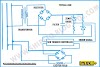
5.2) Question: A 440V,
10KW, 0.8 p.f, 3 phase load is supplied as shown. Calculate short circuit fault
current at the load and at the main switch board. (8 Marks) (Mar, Apr 2018)

Solution:
Short circuit fault location is load terminal
So, the total impedance = Zf = 0.025 + 0.01 + 0.015 =
0.05 Ω
Short circuit fault current = If = V/Zf
= 440/0.05
=8800A
So, prospective fault current level at the load is 8800
A
If, short circuit at the main switch board
The fault current = If = V/Zf
= 440/0.025
=17600A
So, prospective fault current level at the load is
17600 A
Answer:
Prospective fault current level at the load is 8800 A
Prospective fault current level at the load is 17600 A
5.3) Question: What
would be the ohmic value of the NER to limit the earth fault to the full load
rating of a 2 MW, 0.8pf, 3.3KV, 3 phase AC generator? (4 marks) (AUG, SEP, OCT
2018, JAN, Apr 2019)
Solution:
VL = 3.3KV, P = 2 MW, cos ɸ
= 0.8
P = √3 VL IL cos ɸ
So, the generator full load current is
IL = 2*1000 / √3 * 3.3 * 0.8
= 437A
Under E/F condition a phase voltage of the generator
winding will be
VPH = 3300/√3 = 1905 V drives the fault
current through the NER. So, its ohmic value has to be 1905V/437A = 4.4 ohm.
Answer:
The ohmic value of the NER has to be = 4.4 ohm
5.4) Question: A permanent
magnet moving coil instrument has a coil of dimension 15mm x 12mm. the flux
density in the air gap is 1.8 x 10 -3 wb/m2 and the spring constant is 0.4 x 10 -6 Nm/rad. Determine the
number of turns required to produce an angular deflection of 90° when a current
of 5 mA is flowing through the coil. (8 marks) (Oct 2018)
Solution:
Area A = 15 x 12 mm2
= 180 x 10-6 m2
Flux Density B = 1.8 x 10⁻³
wb/m2
Spring Constant K = 0.4 x 10⁻⁶ Nm/rad
Angular Deflection θ = 90° = 1.5708 radian
Current I = 5mA = 5 x 10⁻³
Amp
Deflection Torque Td = NBA I
= N x 1.8 x 10-3 x
180 x 10-6 x
5 x 10-3 N-m
= N x 1.62 x 10⁻⁹
Controlling Torque Tc = K θ
= 0.4 x 10-6 x 1.5708
= 0.62832 x 10-6
= 628.32 x 10⁻⁹ N-m
for the final steady state position,
Td = Tc
N x 1.62 x 10-9 =
628.32 x 10⁻⁹
N = (628.32 x 10⁻⁹) / (1.62 x 10⁻⁹)
So, N = 387.85 ≅ 388 turn
Answer: the number turns N ≅ 𝟑𝟖𝟖 turn
5.5) Question: A coil
having a resistance of 10 ohm and an inductance of 0.15 H is connected in
series with a capacitor across a 100V, 50Hz supply. If the current and the
voltage are in phase what will be the value of the current in the circuit and
the voltage drop across the coil? (10 Marks) (Jul 2019)
Data Given:

Input Voltage V = 100V Frequency f = 50Hz
Coil Resistance R = 10 Ω Coil Inductance L = 0.15H

Solution:
XL = 2πfL
= (2x22x50x0.15)/7
= 47.14 Ω
Coil Impedance Zc = √R2 + XL2
= √102 + 47.142
= 48.19 Ω
Therefore Current and Voltage Phase is same
So, Impedance of Total Circuit Z = R = 10 Ω (∵ Z =10 + j 47.14 – j 47.14)
Supply Current I = V/Z
= 100/10 = 10 A
Voltage across the coil = I x Zc
= 10 x 48.19
= 481.9
Answer:
Supply Current I = 10 A
Voltage across the coil = 481.9 V
CHAPTER 6: ELECTRONICS
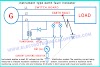
6.1) Question: Diode
half-wave rectifier supply a resistive load of 100Ω from a 100Vac R.M.S.
voltage source. The diode is a resistance of 5Ω during conduction state.
Calculate (i) The DC output voltage (ii) DC average load current. (8 Marks)
(Jan, Apr, Jul 2019)
Given Data:
Vs = 100VAC (rms)
RD = 5Ω &
RL = 100Ω
Solution:
So, Vsm = √2 x Vs = 141.4V
Assume that PN Diode is Silicon, so, VB = 0.7V
Let Maximum Load Current = ILM
So, ILM = Vsm
–VB / RD + RL
= 141.4 – 0.7 / 5 + 100
= 1.34 Amp
Now, VLM = ILM x RL = 134V peak
(i) Let DC output voltage = VLdc
So, VLdc = VLM / π
= 0.318 x VLM
= 0.318 x 134
= 42.6V average
(ii) Let DC average Load Current = ILdc
So, ILdc = ILM / π
= 0.318 x ILM
= 0.318 x 1.34
= 0.426 Amp average
Alternate Method
ILdc = VLdc / RL
= 42.6/100
= 0.426 Amp average
Answer:
(i) The DC output voltage = 42.6 V average
(ii) DC average load current = 0.426 A average
Solved by The senior Electro Technical Officer Mr. Mobin ETO
Previous Part> Chapter 1 and 2


6 Comments
THANK U SIR.
ReplyDeletea 100 kva, 1100/220 v, 50 hz, single-phase transformer has a leakage impedance of (0.1 +0.40) ohm for the h.v. winding and (0.006 + 0.015) ohm for the l.v. winding. find the equivalent winding resistance, reactance and impedance referred to the h.v. and l.v. sides.
ReplyDeleteneed solution
A 4-pole lap wound DC shunt generator has an open emf of 250v when the flux per pole is 0.08Wb and the speed is 10rps. The speed of the generator is reduced to 10% and the flux per pole is increased by 5% when the generator supplies a load of 100A. determine terminal voltage, if the armature resistance is 0.06Ω and the new total field circuit resistance is 200Ω
ReplyDeleteDear Sir
ReplyDeleteCan u please send me the latest eto written question papers please sir. Email: happyhoque@yahoo.co.in
Nicce post
ReplyDeleteHere I get very nicely explanation about.our doubt.thank you sir .
ReplyDeleteWe love to hear your comments on this article, so that we may better serve you in the future.