


Introduction
The transformer is a static device used for transferring
electrical power from one circuit to another circuit without changing frequency
Transformer works on the principle of electromagnetic
induction (Mutual induction) which states that any change in flux linking with
the coil, EMF is induced in the coil.
The transformer consists of two coils or windings which are
electrically separated but linked through a common magnetic circuit.
The two coils have high mutual inductance. If the current in
one coil is changed then an EMF gets induced in the other coil.
The winding which is connected to the supply side is called
primary winding and the one which is connected to load side is called secondary
winding.
The primary winding is connected to alternating voltage and the alternating current which produces alternating flux and this flux links both
the primary and secondary winding. Hence according to faraday law of EMI, mutual
induced EMF is developed in the secondary winding. This EMF drives the current
if the secondary winding is connected to the load thus the electrical power is
transferred from one circuit to another circuit
Types of transformer
Based on the construction of the core
- Core type
- Shell type
Core type transformer
- Windings are placed on either limb
- Windings surround core
- Natural cooling is possible
- Winding cross section can’t be thick
- The core is rectangular and is made up of silicon steel, windings of copper
Shell type transformer
- Core surrounds winding
- No natural cooling
- Cross-section of winding can be thicker
- Both primary and secondary winding is placed on the central limb
Losses in Transformer
- Iron losses – hysteresis, eddy current
- Copper losses
What is Hysteresis Loss?
It is due to magnetisation and demagnetisation of the core
which is produced by alternating flux. During this process, some amount of
power is lost which is hysteresis loss
For silicon steel, hysteresis coefficient is very less, so
it is used for core construction the minimise the loss.
What is Eddy current loss?
Eddy current losses are because of circulating currents or
eddy currents in the metal block. Eddy currents are set up by induced EMF. To
reduce the losses, laminated construction is done to the core thickness of
lamination.
Copper loss
These are due to power wasted in the form of I2R losses due
to the resistance of the primary and secondary windings
It can be minimized by reducing the resistance of windings
i.e. by increasing the cross-sectional area of windings.
Ideal transformer
- It has no losses
- Winding resistance is zero
- Leakage flux is zero
Voltage regulation of transformer
Voltage regulation of the transformer is defined as a change
in the magnitude of terminal voltage from no load to full load expressed as a %
of the no-load voltage
Voltage regulation = [(no-load voltage – full load voltage)
/ (no-load voltage)] x 100
All-day efficiency of transformer
The ratio of output power to input power is defined as the
efficiency which is the power efficiency. But for special types of the
transformer, this may not measures the correct performance
The special types of transformer used for industrial and
commercial loads are distribution transformer
The load on such transformer varies considerably during the
period of the day. But the primary of the transformer is energised at it is
rated voltage for 24 hours to provide continuous supply to the consumers.
The core loss depends on the voltage which takes place
continuously whether the load is tnt or not whereas copper loss depends on the
load condition at no load copper loss is negligibly small while on the full load
it is at rated value. So there will be no measures of true efficiency. In such
a transformer, the energy output is calculated in kWh.
Energy spent in supplying to various losses is also
calculated in kWh. Output to total energy thus the ratio of total energy input
is called as energy efficiency or all-day efficiency.
All-day efficiency = energy o/p during a day kWh / energy
i/p during a day kWh
All-day efficiency = energy o/p during a day (kWh) / energy
o/p in kWht (energy spent in supplying the losses)
Construction of Three phase transformer
The three-phase transformers can be core or shell type. The three
core type single-phase transformers can be combined to get a three-phase core
type transformers and similarly shell-type also
Advantages of single three-phase transformer
- A 3 phase transformer of occupies less space for the same rating compared to a bank of 3 single-phase transformers
- Its weight is less
- Cost is less
- Only one unit is required to be handled which make it easy for the operator
- The core will be of smaller size and the material required for the core is less
- The overall structure and installation of a single three-phase unit is simple
Bank of three single phase transformers
Three single-phase transformer are connected together to
have a three-phase transformer. The 3 single-phase transformers from a bank
have identical ratings.
In a bank of 3 single-phase transformer, the phases are
electrically connected but the three magnetic circuit circuits are independent.
Advantages of Bank of three single-phase transformers
- When one of the transformers is out of service then also the system separations are possible with remaining two transformers using Y-Y connections at induced capacity.
- It is possible to have one transformer in a bank with a higher KVA rating than the other so that unbalanced load can be supplied.
- In the bank of three single-phase transformers, only one single-phase transformer is to be kept spare rather than to keep a where 3 phase unit which is expensive. This requirement of standby is less in case of bank of 3-single phase transformers.
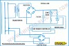
Three-phase transformer connections
The primary and secondary of three-phase transformers can be
connected in different ways such as star and delta connection.
The following types of connections are used
- Y-Y connection
- Δ-Δ connection
- Δ-Y connection
- Y- Δ connection
- V-V connection or open delta
- Scott connection or T-T
Advantages of Delta – Delta [Δ-Δ] connection in transformer
- In order to get the secondary voltage is sinusoidal, the magnetising current of transformer must contain 3rd harmonic content.
- The delta connection provides a closed path for the circulation of 3rd harmonic component of current.
- The flux remains sinusoidal which results in sinusoidal voltage.
- This type of connection can be used for supplying unbalanced load also.
- Due to Δ connection, Vph is same as VL but Iph = 1/ root 3 IL
- Therefore the cross-section of winding is very less, this makes the condition economical for a low voltage transformer.
- If there is a bank of single-phase transformers connected in Δ-Δ and if one of the transformers is disabled, then the supply can be continued with remaining two transformers with reduced capacity.
Disadvantages
It is not suitable for 3 phase 4 wire system.
Labelling of transformer terminals
For high voltage winding, upper case letters are used and LV
windings by lower case letters.
Feature of silicon steel
Silica + pure steel = silicon steel
Silicon steel belongs to Ferromagnetic materials among all
magnetic materials Ferro is a superior magnetic material.
Silicon steel allows low reluctance and high permeability.
Permeability-conductivity-analogies
Silicon steel has low hysteresis coefficient.
If the full load current is 100amps, what would be the starting current when connected in DOL, Star Delta and Auto Transformer?
- In DOL starter it is 5 times full load current i.e. 500 A
- In Star Delta one by third of DOL starting current 500/3 = 166.66 A
- In autotransformer, x^2 × DOL starting current
- X is tapping percentage
- 50% tapping means x is .5
- I.e. (0.5) ^ 2 × 500 is 125 A
- Autotransformer is depended upon tapping. 25 to 100amps.
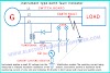
Why secondary of CT should not be kept open?
Since we know that CT is a step-up transformer. So if the secondary side is open then it will create a very large potential difference
between the open ends and which will cause medium to ionise and produce arc and
can lead to a fire. So it's shorted and not left open.
It also becomes a hazard to personnel.
Transformer safeties?
- Ventilations for Air Cooling
- Mechanical interlock for avoiding paralleling two transformers.
- Earthed System.
- Breaker protection
- Fuses.
- Isolation arrangements.
Why can't we use step-up transformer instead of a transistor for voltage amplification?
Because if the Transformer steps up the voltage and at the same time
reduce current because transformer power is always the same in primary and
secondary. So there is no power gain but in a transistor, we amplify signal same
time we can achieve power gain also.
What is Isolation Transformer and what is its function?
An isolation transformer is used to isolate the two circuits
electrically by providing galvanic isolation between them.
Isolation transformers block transmission of the DC
component in signals from one circuit to the other, but allow AC components in
signals to pass.
Isolation transformers are used for impedance matching to
get the most efficient power transfer between stages and to keep different
stages electrically isolated to prevent ground loops.
Isolation transformers prevent harmonics from transferring
from one side to the other side.
Applications:
- Telecommunication equipment
- Remote control equipment
- Computers & peripherals
- Analytical instruments etc.
How do you identify the primary and secondary winding of a transformer? When there is no marking
- We can identify by observing the connecting cable dia. 440 side cable having less dia as compared to 220 sides.
- For step-up transformer low voltage side is primary and high voltage side is secondary.
- For a step down high voltage side is primary and low voltage side is secondary,
- The technical terminology is HT and LT instead of the primary and secondary side. The HT/LT may be primary or secondary.
- In case of a step-down transformer, primary windings must have more length than the secondary windings. So, obviously, the winding having more length will have more resistance than the other.
- In short, check the resistance of both windings and the windings having more resistance will be the primary one.
Why transformer should not be connected star - star?
We
can connect is Y-Y configuration also. But every configuration has its own
advantage and disadvantage. In Y if the fault occurs in any phase we have to
isolate whole winding but in Delta, if the fault occurs in one phase we can run the
transformer in V (open delta) connection having 57.7% efficiency. In star connection, harmonic generation is more as compared to delta
Also,
in Y-Y connection the 3rd harmonics present in supply, to eliminate 3rd
harmonics there is a requirement of an additional 3rd winding which connected in
delta called tertiary winding in Y-Y connection transformers.
What happens when we use a copper core instead of iron steel core in the transformer?
As
copper is a paramagnetic material it has low permeability as compared to iron.
Hence to maintain the same flux in core transformer draw more current and
windings damage.
What will happen if we connect dc voltage to the input of a transformer?
When a DC voltage is applied to the primary winding of a
transformer, due to low resistance, the winding acts as a short circuit across
the terminals of the DC source that lead to the flow of heavy current through
the winding resulting in overheating of the winding. Eventually, the source or
the winding will be damaged. The effect of current on winding depends on the
applied DC voltage, rating of the transformer, winding resistance and how
powerful the DC source is. “Nothing will happen if 5Vdc is applied to a 50KVA
transformer!
In order to replace ammeter why should we open CT?
The CT converts current in the range of 1A or 5A from a
higher value. That is high ampere current to lower ampere rating by using step
up transformer
As the voltage gets stepped up this can lead to arcing at
the secondary if left open while working.
To avoid this, we short the secondary of CT.
How do you carry out the Transformer changeover on ship?
- The changeover should be carried out in anchorage or port
- Note down the parameters of working transformer
- Carry out IR test for standby transformer
- Make sure everything's perfect
- Inform to bridge and must shout down which are not get supply from ESB and UPS
- After having to carry out the changeover operation
- Note down parameters and compare to previous work
- transformer. If everything perfect and we have to switch ON back to which are shout down.
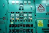
What are the types of transformer using in the ship?
- Power distribution transformer (High Rating) – for step down, lighting, and 220VAC consumers
- Potential transformer (Low Rating) – indication lamp and instrumentation
- Current transformer – instrumentations circuits and metering
- Isolation transformer – PCB and control circuits
- Ignition transformer – boiler and incinerator
- Low voltage to high voltage with Low current spark
- Autotransformer – Starter
- Welding transformer – Welding machine


5 Comments
Thanks for ssharing this
ReplyDeleteHow will you order a transformer ? Please answer this.
ReplyDeletewhere we use step up transformer
ReplyDeleteCan you tell me safety of transformer.
ReplyDeleteCan an earth fault from the primary side of a transformer transfer to the secondary side
ReplyDeleteWe love to hear your comments on this article, so that we may better serve you in the future.