

AVR QUESTIONS AND
ANSWERS FOR ETO ORAL EXAM
How we will get to know AVR is faulty by what checks we will do for confirmation exactly. Or if you suspect the AVR is faulty, how will you confirm?
SYMPTOMS
- No output voltage
- Low or high output voltage
- Significant voltage changes with changes in output current
- Run excessively hot
- Excessively noise
- Uncontrol voltage
- Diagnosing a faulty AVR is done by a process of elimination.
- Exciter part
- Rotating diode part
- Main stator part
- Cable connection and continuity
- If all are intact then the AVR is faulty and will need to be replaced.
What is the output voltage of AVR's step down transformer?
Depends upon sensing voltage
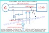
AVR circuit diagram and explanation, SCR triggering
Thyristor-Based Electronic AVR Circuit Diagram
The direct current
derived from the alternator output through the transformer is rectified and
filtered. Then it is applied to a Wheatstone bridge which has fixed-resistance
on two arms and variable resistances (Zener diode voltage reference) on the
other two.
The Zener operates
in the reverse breakdown mode, as these diodes are manufactured with a Zener
breakdown voltage of very low value. Zener diode voltage remains constant once the breakdown voltage has occurred despite the change in the current. This implies
that changes in applied voltage, while not affecting voltage across the diode,
will cause a change in resistance which permits the change in current. As with
a Wheatstone bridge, an imbalance of the resistance changes the flow pattern and
produces in the voltage measuring bridge an error signal.
The error signal
can be amplified and used to control alternator excitation. Thus it can control
the firing angle of thyristors through a triggering circuit to give the desired
voltage. It can be used in the statically excited alternator to correct small
errors through a magnetic amplifier arrangement. The error signal has also been
amplified through transistors in series, for excitation control.
SCR TRIGGERING
For SCR to start
conducting, it needs two conditions simultaneously. 1. The voltage at anode greater
than cathode 2. Gate signal (current injection in gate).SCR once turned on,
will remain to conduct till the cycle completes.
Firing angle
refers to the phase angle of the ac supply voltage (sinusoidal) when the GATE
current is applied and thyristor turns ON.
For example, if
firing angle is 45 degrees, then up till 45 degrees of the input sine wave it
won't conduct, after that, it'll conduct till the cycle completes (or till the
next current zero, as needed by the designer)
If it's firing
angle is decreased, the SCR will turn on early in the cycle which will result
in the increase in output power, voltage.
If it is firing
angle is increased, the SCR will turn on later in the cycle which will result
in a decrease in output power, voltage.
How will you check AVR?
AVR checks, as guided by the manufacturer, consist of AC and
DC voltage measurements at installed test points
What will you do if the AVR is bad?
Renew the AVR
AVR changeover should only be attempted when its generator
stopped and locked off.
How will you know AVR is malfunctioning?
Check the output voltage of AVR in ideal condition, and
match with manual and then make sure the excitation trimmer setting is as what the manual is telling and if it's not matching then AVR is defective.
Of no voltage is coming out at AVR output terminal is zero.
In ideal condition...then it's defective
Correct operation of AVR
When generators are load sharing in parallel, check for approximately
equal current sharing between the machines. This will indicate the correct
operation of their AVRs
AVR working principle.
It works on the principle of
closed-loop control system.
The output voltage of an AC generator obtained through a potential transformer
and then it is rectified, filtered and compared with a reference. The
difference between the actual voltage and the reference voltage is known as the
error voltage. This error voltage is amplified by an amplifier and then
supplied to the main exciter or pilot exciter.
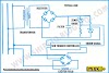
AVR block diagram. AVR control Range for the Main generator and emergency generator

The voltage sensing unit transforms down,
rectifies and smooth the generator output voltage. This produces a low voltage
DC signal proportionate to AC generator voltage.
In the comparator unit, it is compared to the set value (DC
value produced by the reference unit of the Zener diodes and resistance). The
correction is then amplified and through thyristor control is used to alter the
alternator field current in order to reach the set voltage value.
This is its steady-state voltage regulation. Transient
voltage dip is usually limited to 15%
for a specified sudden load change with recovery back to the rated voltage
within 2 seconds.
What is AVR? Role of Zener diode in AVR
Reference unit of the Zener diodes, The Zener operates in the
reverse breakdown mode, as these diodes are manufactured with a Zener breakdown
voltage of very low value. Zener diode voltage remains constant once the breakdown
voltage has occurred despite the change in the current. This implies that
changes in applied voltage, while not affecting voltage across the diode, will
cause a change in resistance which permits the change in current. As with a
Wheatstone bridge, an imbalance of the resistance changes the flow pattern and
produces in the voltage measuring bridge an error signal.
CT purpose in AVR
To obtain correct load sharing between parallel running
alternators, the alternator voltage is made current dependent. This is obtained
by the current transformer and a resistance network inside the AVR unit.
AVR operation and how much voltage dip
Transient voltage dip is usually limited to 15%
Explain AVR and SOLAS regulations
A.V.R or Automatic Voltage Regulators are used
in conjunction with the generator for controlling the terminal voltage to give
a steady voltage under varying load.
It senses and controls an A.C generator’s output
voltage within (+ or -) 1 to 2%.
There are following main functions of an AVR
- Controls the voltage of the system and operation of the machine nearer to the steady-state stability.
- It divides the reactive load between the alternators operating in parallel.
- The automatic voltage regulators reduce the overvoltages which occur because of the sudden loss of load on the system.
- It increases the excitation of the system under fault conditions so that the maximum synchronizing power exists at the time of clearance of the fault.
An AVR will control the generator’s voltage
to 2.5% (or better) of its set value over the full load range. This is its steady-state voltage regulation.
15% of voltage dip should be brought back into the range of
+ or – 2.5%
In special cases where unusually large surges are expected
(e.g. from heavy-duty cargo cranes) the generator / AVR performance limits may
be extended.
What is AVR output voltage range for an emergency generator and turbine generator?
If the AVR is defective, can it handle the additional load?
No
REASON
An AVR works on the principle of the closed-loop control system. It used to regulate the output voltage of the
generator and accordingly control the field circuit of the generator. If the AVR is
defective then there will be incorrect feedback to field circuit which might
lead to over and under-voltage scenarios.
AVR components, how much voltage is after step down transformer and purpose of comparator
In a process control of voltage regulation by electronic AVR involves
the following components
Voltage
sensing unit – to check the present value of the voltage- steps down the voltage rectifies and smoothes the generator output. Producing a dc signal proportional to the generator terminal voltage.
The
comparator unit – to check error .i.e. difference in voltage- compares this dc signal with a set dc value. Giving an error output
amplifying
unit – to amplify the error signal-the error signal is amplified and made
suitable for driving the thyristor circuit
correcting
unit – to apply actions to process control as per error to get desired
output voltage
Purpose of comparator
The comparator unit compares this DC signal with a set DC
value giving an error output
How the AVR will damage?
- Unstable Engine Speed of the Generator
- Overload (Overcurrent)
- Big Surge of Power
- Short Circuit
- Life Time
AVR types
- Carbon
pile regulator
- Vibrating
contact regulator
- Static
A.V. R.
- Rotating
sector
- Multi
contact
- Magnetic
amplifier
- Electronic
amplifier
The output value of AVR
The AVR Output Voltage to Exciter Stator usually ranges from
13Vdc - 60Vdc, the voltage applied to the Exciter depends on how much voltage
(Sensing) the AVR receives from the generator voltage.
In loaded condition 90-95V DC, ideal condition 60-65V DC
AVR functions during surges.
AVR droop question
Droop % = (No load rated current - full load rated current)
/ No Load Rated current
Droop Current transformer is used to maintain the reactive
power of the generator. Droop CTs are ordinary current transformer which is
used only for AVR.
AVR controls the reactive power of the generator with the
help of Droop CT. At the same time, the power factor can be adjusted with the
help of droop CT reference only.
This adjustment is performed by adjusting the excitation current of the generator. When you increase the excitation current
to the generator, which generates more reactive power and when you decrease the
excitation current the generator produces less reactive power vice versa.
If the AVR droop is less- the generator will share more KVAR-so
less kW. So more loss in the system...and Power factor will be more lagging.
What if change connection direction of exciter field +F1 and - F2 in AVR?
Then the direction of current will change through an exciter
winding and also the direction of the magnetic field will change if the stator field and rotor field
are in the opposite direction flux generated will be reduced and reduced flux means the reduced voltage that we will get at the alternator terminals
If we change the polarity of dc coil direction of current
flowing through it changes
What is the requirement of an emergency generator AVR setting?
How AVR is maintaining the voltage?
It controls output by sensing the voltage from the generator
terminals and comparing it to a set voltage reference. The error signal is then
used to adjust the field current by increasing or decreasing the current flow
to an exciter stator, which in turn will lead to a lower or higher voltage at
the main stator terminals. So that we can regulate the terminal voltage
In AVR can we use a diode in place of thyristor? Explain?
No
The diode is an uncontrolled rectifying device
A diode is a two-terminal unidirectional device. This means it
conducts current only in one direction.
But SCR or thyristor is a three-terminal device that anode,
cathode, and gate. SCR is a good device for controlling purposes as in Scr we can
control the Scr by just changing the firing angle.
In simple words, we can say that the firing angle is a point
where we provide the required voltage at the gate terminal of SCR so that it
starts conducting.
Can we check voltage near AVR in running condition?
Why only D.C is used for Excitation in Alternators?
Excitation voltage or current is supplied to the field
windings of a rotor to produce a static magnetic field. If we use alternating
current instead of direct current; we will get a fluctuating magnetic field.
This will generate alternating magnetic flux in the stator windings leading to
unpredictable and unstable voltage and power supply which may cause distortion
and high risk for burning armature windings. Even if we somehow tap the output
it won’t be pure sinusoidal three-phase supply. This is why the field windings
of a rotor must be excited by direct current to avoid all those disadvantages.
Setting in AVR
Ramp Potentiometer – To set the time taken for the initial the buildup of the alternator voltage to its rated value ( 1-3 Sec) ranges from 1-8sec
Droop setting – To enable proper sharing of KVAr
load during paralleling alternators. The common method of KVAr sharing is
to create a generator voltage characteristic which falls with a decreasing PF
(increasing KVAr). A current transformer in the Blue Phase
provides a signal that is dependent upon the current phase angle to the AVR.
The CT has a burden resistor and the percentage of the resistor’s voltage
(Droop Setting) is added to the AVRs Circuit.
Under Frequency Roll Off – To give an indication when the
frequency falls below a set value ( 57 Hz for a 60 Hz alternator)
Dip Setting – To adjust the Volt/Speed
characteristic
Dwell setting – Provides a time delay between the
recovery of voltage and recovery of frequency
All the above settings are set
during the initial commissioning and are not to be meddled with
indiscriminately
Protection in AVR
EXCITATION PROTECTION
An AVR supplied by PMG inherently
delivers maximum excitation power during “Line-Line” or “Line-Ground”
short circuits since output voltage dropdown
drastically during the above faults.
To protect the windings from such
over-excitation, an excitation trip acts after a pre-determined delay
to cut off such over-excitation.
The trip setting should be such that
it does not operate when the generator is on full
load or when a small overload occurs.
OVERLOAD PROTECTION
In the event of a loss of
Voltage Sensing input to AVR, the resulting excitation may cause a
Overvoltage at the Generator output.
In such an event, this protection
can provide two signals.
a. “De-excitation” of
Generator
b.
Open signal to the Generator Breaker
The setting should be such that it does
not operate under “no-load” conditions or
during “load shedding”
References:
References:
Please comments! We do take time and effort to answer these questions; if not, what is the point?
We love to hear your comments on this article, so that we may better serve you in the future.


)
8 Comments
We are here always to support you and learn from your blog keep posting such useful stuff... Thank you Mr. MANI
ReplyDeleteThank you so much. And keep support my blog
DeleteThank you so much. And keep support my blog
ReplyDeleteThank you for such vital information
ReplyDeleteNo o/p voltage doesn't mean that the AVR is defected...maybe one of the diodes or you lost the residual magnetism in the coils.
ReplyDeleteThis is one of the best article on AVR till now
ReplyDeleteThe residual magnetism can be checked by insulation Tester.
DeleteEL AVR 90-20 DE GENSET CAT DE 225 KVA 4 OHMS FIELD RESISTANCE SOLO ALCANZA 99 VOLTS ENTRE FASES.
ReplyDeleteAPLICANDO CON BATERIA12 V DC LLEGA HASTA 290 V.
MIDIENDO LA ALIMENTACION DEL EXCITADOR MARCA 4.5 DC VOLTS PERO SOLO ALCANZA LOS 199 V AC ENTRE FASES. ADVIRTIENDO EN EL DISPLAY BAJO VOLTAJE Y SE PARA EL MOTOR. MUCHO AGRADECERE TUS COMENTARIOS
We love to hear your comments on this article, so that we may better serve you in the future.